Individual heat supply systems typically consist of three main components:
Irrespective of the fuel, auxilliary electricity is usually needed to operature pumps and pistons to feed the fuel into the burning chamber and ciruclate the heat exhange medium. Some of the typically used systems are described below.
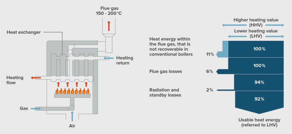
In contrast to the constant-temperature boilers, which e.g. until about the end of the 1970s dominated in Europe, the low-temperature boiler (LT-boiler) can be operated according to the weather conditions, through a modulating boiler temperature between 30 and 75 °C. This allows a considerably higher annual efficiency achieved of about 85% to 90%, compared with only about 70% in case of a constant temperature boiler, but still lower than a condensing boiler.
The condensing boiler is in principle a low temperature boiler, in which an additional heat exchanger is connected in the exhaust stream. This second heat exchanger cools the gas to below the condensation point (natural gas: 56 °C / gas oil: 47 °C). Thus, in addition, the (so-called latent) heat that is released in the condensation of water vapor, can be used. The relative degree of efficiency (relating to the calorific value) can be raised in this way to about 100% for natural gas and 95% for heating oil. The gas condensing boilers are now considered to be best available technology (BAT). They can usually also be realized in existing buildings through the use of titght and acid-resistant chimney (such as plastic pipe use).
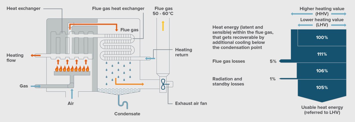
For heating oil as well as for wood pellets condensing boilers are also available, however, associated with higher costs at slightly less additional energy gain of around 6% (wood) and 8% (wood), compared to about 11% energy gain for natural gas (see the table below). To avoid the formation of sulfuric acid while the exhaust gas is condensing, the use of desulfurized fuel oil is required.
| Fuel | LHV → HHV | HHV → LHV |
|---|---|---|
| Fuel oil | 1.06 | 0.943 |
| Natural gas | 1.11 | 0.901 |
| LPG | 1.09 | 0.917 |
| Hard coal | 1.02 | 0.980 |
| Lignite | 1.07 | 0.935 |
| Wood | 1.08 | 0.926 |
The following figure shows considerable energy saving potentials can be realised if old boilers are replaced by best available technology. Especially at warmer outdoor temperatures there is a large efficiency gain. E.g. in central Europe about 65% of operation time is at ambient temperatures higher than zero degree and 85% higher than minus five degree Celsius.

The following figure shows the specific investment costs for the renovation of a heating system are for larger buildings considerably lower than for small systems. Natural gas boiler systems roughly cost between 10 € (for a building of 1500 m2) and 70 € (for a 100 m2 building) per square meter living space.
")
In the case of renewable fuels, the solid fuels and in turn, the renewable resource wood is the most important one. Its various stages of processing are
For all firewood, used in small heating systems, applies that only natural (i.e. untreated) wood may be used, which also should be sufficiently dried before (well-seasoned for one to two years). Typical properties such as water content, bulk density and calorific value are summarized in the table below for various wood assortments. As you can see, the heating value is dependent on the type of wood and water content.
| Fuel | Water content (%) | Bulk density (kg/Sm3) | calorific value (kWh/kg) | Heat oil equivalent (litre/Sm3) |
|---|---|---|---|---|
| Beech- air dried | 20 | 280 | 4.1 | 115 |
| Spruce – air dried | 20 | 230 | 4.2 | 97 |
| Beech- green | 50 | 460 | 2.2 | 101 |
| Spruce - green | 50 | 330 | 2.3 | 76 |
| Saw dust | 40 | 260 | 2,6 | 68 |
| Wood shavings | 25 | 120 | 3,7 | 44 |
| Bark | 60 | 800 | 1,9 | 152 |
| Wood pellets | 10 | 650 | 5,0 | 325 |
| Wood log | 20 | 400 kg/Rm | 4,1 | 164 l/Rm |
Split log boilers
Split logs are usually wood residues, which are obtained in the extraction of timber as a non-usable proportion and which can be simply sawn or split by axe or saw to an appropriate size (usually 30 to 100 cm length). Suitable wood species are coniferous wood (e.g. pine and spruce) and wood from deciduous trees (e.g. beech and oak) that is more expensive but also more energy-rich, based on its volume. Normally, firewood is the least expensive wood fuel, but the furnace must be manually charged about every four to eight hours and is therefore far less comfortable than wood chip or pellet systems. The following figure illustrates the functional principle of the two-stage energy conversion in a log gasification boiler.
In the first phase - the low-temperature pyrolysis phase - the log is gasified in the firebed with low oxygen primary air. An induced draft fan sucks the pyrolysis gases into the combustion chamber where they burn with preheated secondary air (high-temperature oxidation phase) and heat the hot water via a heat exchanger.
Split log boilers can’t be regulated via fuel feeding in their performance, however, a limited power control is possible by changing the combustion air, in modern microprocessor-controlled equipment down to up to 50% of nominal power. Lambda probes can also reduce the emissions. The installation of a storage tank with a specific minimum size of between 50 and 100 litres per kilowatt rated power is recommended in order to go in terms of efficiency and emissions at the optimum operating point. Log wood boilers are mainly operated in the power range between 15 and 50 kW. The gasification principle is not only available for central heating boilers but also for some innovative wood ovens for single room heating (see figure below). It guarantees a mostly complete, clean and energy-efficient combustion. Nominal energy efficiency factors of 90% are achievable with this technique.
Wood pellet boilers
Wood pellets are dried to a maximum of 12% residual moisture, and normalized as wood dowel shaped pellets from untreated wood waste. They are usually produced from sawdust and wood shavings and shaping of the wood processing industry. The pellets have a diameter of 4 to 10 mm and a length of 20 to 50 mm. To ensure quality, they should comply with harmonised standards, e.g. the European norm DIN EN 14961-2, DINplus, ENplus or similar. One advantage of the pellets is their high storage density and good transport logistics: Their energy content is 5 kWh/kg (≈ ½ litres of oil equivalent). Referred to the volume its energy density is about four times as large as the wood chips. Pellets can be delivered in large quantities loose in silo-tanks and in smaller quantities in sacks. Because of the low ash content of normed pellets (< 1.5%) ash must be taken from the boiler only four or five times a year. It can be used as fertilizer or disposed in the organic waste or household garbage.
Pellet heating systems are offered as single ovens (about 2 to 15 kW, heat use due to design primarily in the installation room) with a small integrated pellet storage container or as central heating systems (heat use only outside the installation room) with automatic feeding via a suction or feed screw of a pellet hopper. The latter are installed in a boiler room and are comfortable to operate similar to conventional central oil or gas heaters. In the living room established individual ovens can - in an enlarged version - additionally be equipped with water bags and be connected to a heating system. In this case they may supply about 80% of the heat to the radiators in other rooms and for domestic hot water production, the residual 20% directly heats the room of installation. This version is ideal in combination with a solar thermal system that takes over the hot water supply in the non-heating period.
Pellet heating systems reach - because of their standardised fuel and uniform fuel combustion - both the highest efficiency (up to 95%) as well as the best emissions from wood combustion systems considered here. Pellet boilers, in addition to the standard version as a low temperature boiler, are now available in condensing technology.
Heat storage tanks are used to avoid unnecessary frequent starting-up of the heat generator (e.g. burner of a boiler, compressor of a heat pump or motor of a CHP unit). Therefore they support the energy efficient and low air pollution operation of the heat generator. Moreover storage tanks can reduce the required maximum heat output of the heat generator and thus reduce investment costs especially for technologies with high upfront costs like electric heat pumps or CHP units. For the use of solar thermal energy, storage tanks are a prerequisite to match periods of solar heat gains with periods of heat demand by storing solar energy for days, weeks or months (seasonal storage). Especially for solar heating systems, stratified storage tanks are to be recommended, because they allow storing heat also at lower temperature level. Storage tanks lower investment costs by using smaller heat generator capacity (e.g. heat pumps or CHP units). They Temporally decouple heat generation from heat demand (essential for solar systems) and take over the function of a hydraulic switch (for coupling two heating sections with different flow rates). A storage tank can be designed to provide the domestic hot water (DHW), the hot water for the heating or both combined. Dimension and type have to be selected specifically according to the actual needs of the entire heating system of a building.
Increasing the efficiency of storage tanks
The general recommendation for the optimization of the heat storage is to use and reduce the “standby losses”: For that the storage tank should be installed within the thermal envelope of the building and its encasement should be heavily and gapless insulated (e.g. insulation with at least 80 to 100 mm Polyurethane). In the following some options for improving the partial energy efficiency of heat storage are listed. Keep in mind that for all parts of the heating system an appropriate dimensioning is essential.
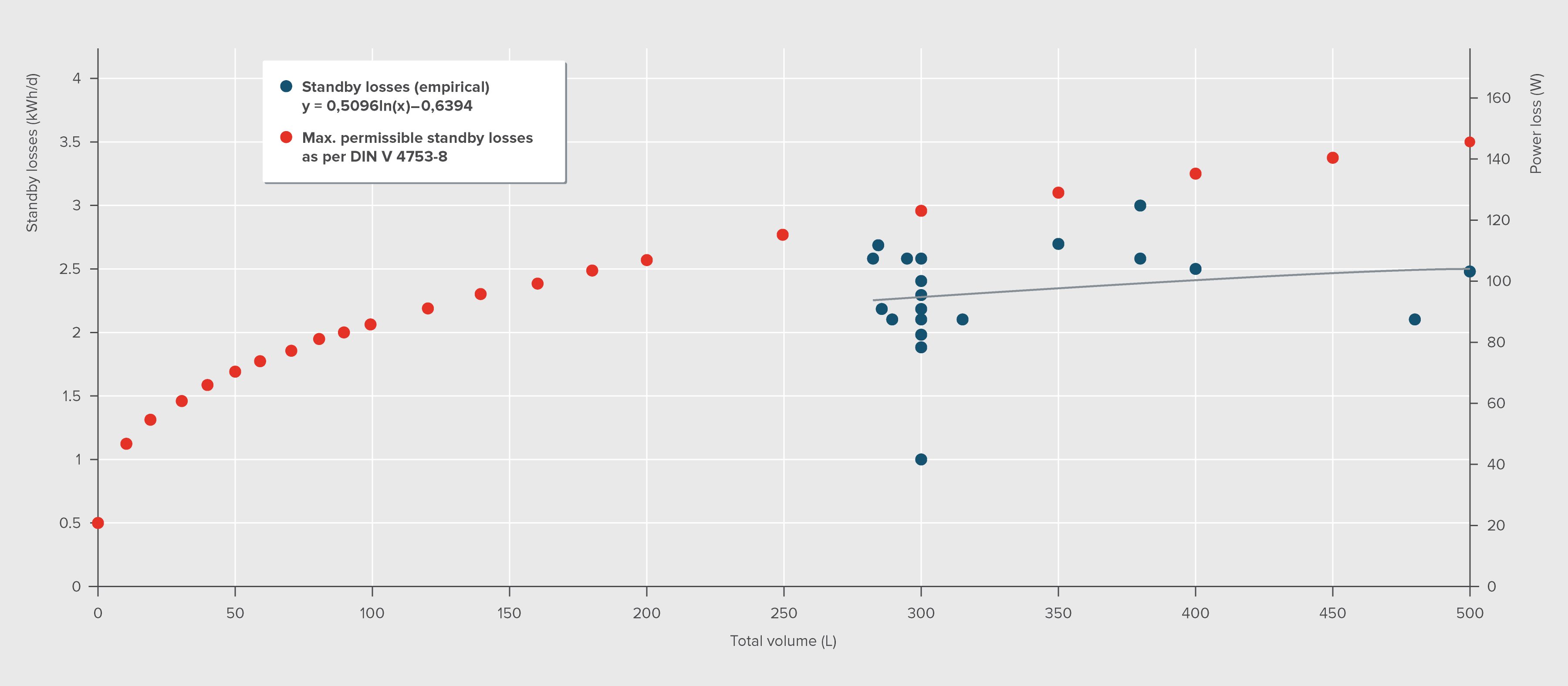
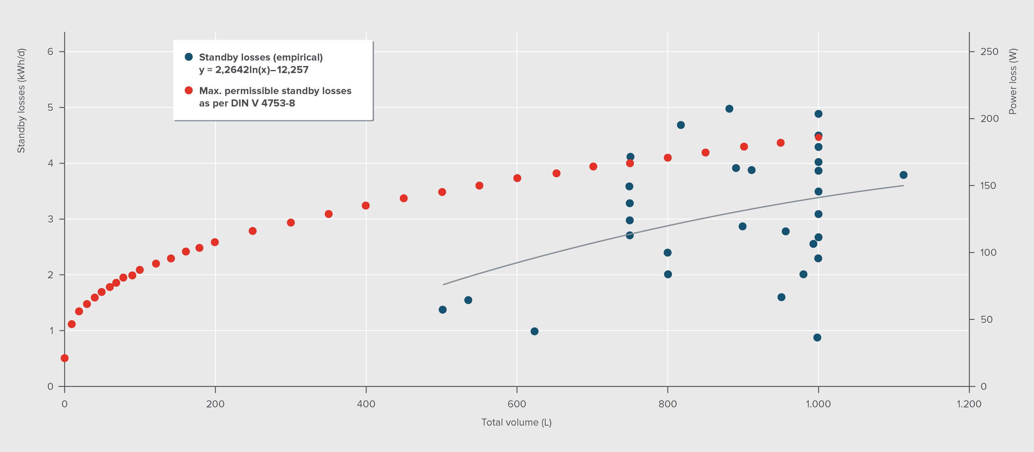
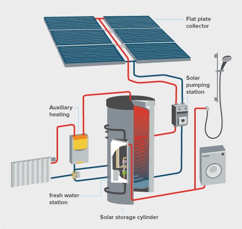
The load times for the storage tank should be set by an expert according to the proposed charging strategy. A loading strategy could be, for example within solar thermal systems, to avoid the filling of the water storage by a backup heat generator in times of potential solar yield (i.e. around midday). Another precept is: The lower the temperature level in the tank, the lower are the thermal losses. Moreover the efficiency of some heat generators, namely electric heat pumps, drops significantly with higher water temperatures. The storage design temperature is determined by the required flow temperature of the heating system. In case of DHW storage additionally hygienic aspects have to be considered: For small systems (≤ 400 litre of storage volume and a content of less than 3 litre in the pipes between the storage and the tap) as a rule 50 to 55°C are sufficient. Bigger systems (> 400 litre) should be heated once a day to a temperature of at least 60°C to avoid legionella colonies growth (DVGW.de, 2016). Fresh water stations (see figure below-right) generate DHW in an instantaneous flow and thus minimize hygienic risks.
 and principle of a solar buffer storage tank with fresh-water-station (bottom)")
Technological foresight
In the future thermal heat storage can play an important role to enable the transition to a more energy efficient heat supply with higher renewable shares. Therefore it is essential to develop alternative heat storage materials, highly efficient insulation concepts (like vacuum insulation) as well as large scale and seasonal storage concepts. In the following such innovative approaches are illustrated. Water has a high heat capacity, is cheap and nearly everywhere available and thus the most common storage medium for heat storage. Furthermore there are several other potential options for (future) residential heat storage or for mid- to large-scale heat storage systems e.g. for block supply and local- or district heating (see table below) (BINE.info, 2016).
| Sensible heat | Sensible heat | Latent heat | Latent heat | Chemical energy/Reaction heat |
|---|---|---|---|---|
| Fluid | Solid state | Solid-state <-> liquid | Liquid <-> gasiform | e.g. sorption storage (Metal hydrides, silica gel, zeolite) |
| Water/Aquifer | Rock / gravel / sand / concrete | Melting (salt hydrate, paraffin, wa-ter/ice) | Steam | - |
Latent-heat or PCM (Phase Change Material) storage devices use the very high specific thermal storage capacity of materials that change its aggregation state (e.g. melting salt). The main advantages of this storage concept are the compact structural shape and its ability to store heat over a long time with low heat losses. But they are still in a early market phase and compared to the water systems considerably more expensive.
Vacuum storage tanks
A new approach for minimizing thermal storage losses in spite of compact form is the vacuum insulation. Similar to a vacuum bottle these steel tanks are double-walled and evacuated in the space between. The space is filled with packing materials of special thermo-dynamic properties to absorb the mechanical forces caused by the vacuum. The storage losses of 2 Watt per Kelvin (or 0.2 °C per day at a temperature difference of 90°C) for a 16 m3 vacuum tank are about 80% lower than those of conventional tanks insulated with mineral wool. Thus this new approach allows also seasonal storage with acceptable thermal losses even for smaller storage volumes. First pilot projects with 11 m3, 26 m3 und 48 m3 vacuum steel tanks have been implemented in Germany (Banse, S. 2011).
Heating systems also consume auxiliary energy, for example for burner fans, control units and circulation pumps. Especially the electricity consumption of the circulation pump can be considerable. As a rule of thumb, the total electric power consumption (in kilowatt-hours) of a traditional heating system equals 2.5 to 3% of the fuel consumption, compared to only 1% within a state-of-the-art high quality installation. This represents a saving potential of up to 300 kWh per year of electric power for an average single-family house. General recommendations for the optimisation of heat distribution are:
Examinations of existing heat distribution systems show optimization potential in many aspects (cf. Boileff.de, 2008):
Correct choice and design of circulation pumps
Correct
choice and design of circulation pumps can realise savings potential of
60 % electricity in new buildings and up to 90 % in existing buildings.
The recommendations for the energy efficient use of circulators are as
follows (topten.eu, 2011):
The recommended nominal electric power input for a highly energy-efficient circulating pump should be lower than 1‰ (one thousandth) related to the nominal heat output of the whole heating system. High-efficient circulation pumps that, e.g., meet the requirements of class A of the voluntary “Europump” energy label are three times more efficient than conventional pumps and there-fore easily achieve this value (Boileff, 2008). These speed-controlled pumps are equipped with permanent magnet- or EC- (electronically commutated) motors and adapt their performance according to the varying flow or pressure automatically.
Compared to conventional pumps, the installation of a high-efficient circulation pump is about 150 € more expensive, but about 60% of the electricity can be saved. That means, for example, on average 300 kWh or 75 € can be saved per year (at a electricity tariff of 0.25 €/kWh) (Boileff.de, 2008). Hence, due to the short payback period of only 2 years, the usage of more expensive high-efficiency pumps is also beneficial from an economic point of view. The electricity saving potential across the EU-27 is more than 30 TWh per year (topten.de, 2011).
The European Association of Pump Manufacturers „Europump“ has already in 2005 launched a voluntary energy label for circulator pumps, that defines energy efficiency classes from A (best) to G (worst), see Figure 25. Class D expresses the average efficiency of the European pumps offered in the year 2003. From 2013 on, the regulation no. 641/2009 of the European Commission mandates a maximum Energy Efficiency Index EEI of 0.27 or less . The standard will be further stepped up to EEI ≤ 0.23 in 2015. That means that inefficient pumps will be phased out in the EU. Already today circulators with an EEI performance better than 0.20 are commercially available (e.g. see product list of http://www.topten.eu/english/criteria/heating_pumps_ak.html).
| Class | Energy Efficiency Index EEI |
|---|---|
| A | EEI < 0.40 |
| B | 0.40 ≤ EEI < 0.60 |
| C | 0.60 ≤ EEI < 0.80 |
| D | 0.80 ≤ EEI < 1.00 |
| E | 1.00 ≤ EEI < 1.20 |
| F | 1.20 ≤ EEI < 1.40 |
| G | 1.40 ≤ EEI |
Even if a modern high-efficient circulation pump is used, the entire heating system has to be adjusted correctly. Otherwise excessive power consumption, noise problems or insufficient heat output of individual radiators can be the result (Minergie 2007). The required procedure for this optimization process is called “Hydraulic adjustment”.
Field trials have shown that in single- and two-family houses by a correct hydraulic adjustment annually about 8 kWh of heating energy per m2 treated floor area can be saved. A heat distribution system is a network with many parallel flow resistors (pipes, valves, radiators etc.). In this system the prevailing water currents flow through those supply lines with the lowest resistance. Thus, in rooms with the maximum distance from the heat circulation pump there is less flow and therefore less heat output than in rooms that are closer to the heat source. This situation is illustrated in the following figure. The upper heating element is further away from the heat source than the lower one and - as a consequence of the missing hydraulic adjustment - not completely warm.

In this unbalanced case many user or manufacturers just try to solve the problem by increasing the output of the circulating pump. But this is not a sustainable solution, because new problems occur: Inadequate high pump output causes flow noise and high operation costs for pump electricity. Moreover the system’s return temperature increases and therewith the efficiency of the heat generator declines. The right way to avoid or remedy these problems is the hydraulic optimization by setting the radiators flow resistance so that the flow is optimal according to the desired power of the radiator. The flow resistance can be changed by means of thermostats with adjustable valve cores. As a result of a correct hydraulic adjustment the flow rates in radiators closer to the circulation pump are reduced and the thermal comfort in remote rooms improves.
Field trials have shown that in single- and two-family houses by a correct hydraulic adjustment annually about 8 kWh of heating energy per m2 treated floor area can be saved, equivalent to about 10 % of the heating energy. In addition, due to the reduced water circulation, significantly less pump energy is required. In conventional installations with (often oversized) circulation pumps with three or four power levels, the pump can be set to a lower setting. In the case of new heating systems or the replacement of the pump, a smaller new circulation pump can be used. The optimized operation of the circulation pump will save up to 90% of the electric power consumed by the heating system (Minergie, 2007; Boileff.de, 2008).
Improving the energy efficiency of heat transfer to the room (Heat Emitters and Controls)
Significant amount of energy savings can be incurred by improving the efficiency of heat transfer system to the room. General recommendations for the optimization of the control system and the heat transfer to rooms include:
Examinations of existing systems in Central Europe (Germany, Austria) found several optimization potentials for radiators and controls (Boileff.de, 2008):
| Measure | Typical savings compared to the standard (in %) | Additional costs compared to the standard |
|---|---|---|
| Valve bodies designed for a 1 K-control difference (including the use of pre-adjustable fine regulator valves) | Ca. 5 % | No additional costs |
| Programmable thermostat for a timed setback (e.g. for absence or night setback) of a radiator (3-4 Kelvin) with a thermostatic valve body | 5 – 15 % | 50-60 € per programmable thermostat valve |
| Efficient radiators with higher room-side share of radiation | Ca. 5 % | 50-60 € per programmable thermostat valve |
It can be emphasised that the greatest saving potentials realised by intelligent and precise control can be found in existing buildings with their high heat demand. Compared to these, very energy-efficient buildings are more tolerant against improper control or improper operation by the user.
makes energy efficiency in buildings and appliances transparent. For investors, policy-makers and actors involved in implementation and consultancy. Learn more ...


 Buildings Guide
  Policy Guide
  Appliances Guide
  India
India South Africa